All information presented here is intellectual property of Barou.
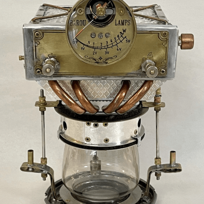
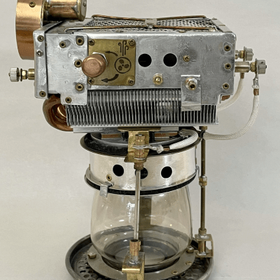
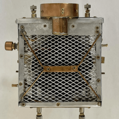
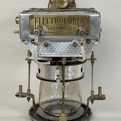
In this section, the presentation of Electrophorus technology and specifics are being displayed aiming to satisfy the curious visitor, to provide insights of Barou’s novelty lamps and to give an idea of the amount of work required in crafting such lighting machines.
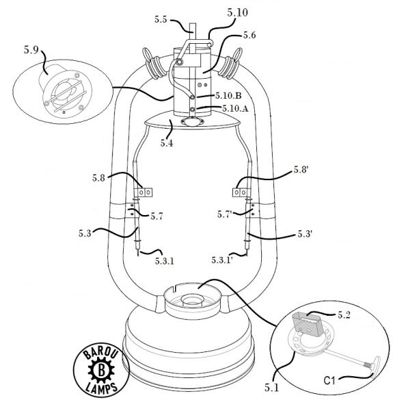
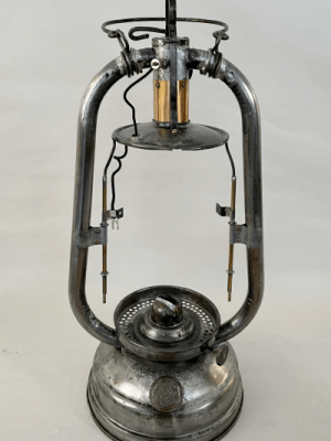
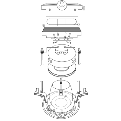
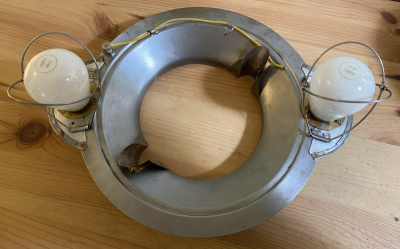
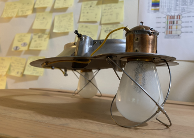
An Electrophorus lamp has two main parts. The generator and the lamp-holder. Moreover, the generator is composed of the chassis utilized and the generator module. The figures illustrated bellow, are part of the filed patent and are explanatory of the components’ function.
It should be said that each Electrophorus lamp has over 50 unique pieces that have to be custom made.
CHASSIS
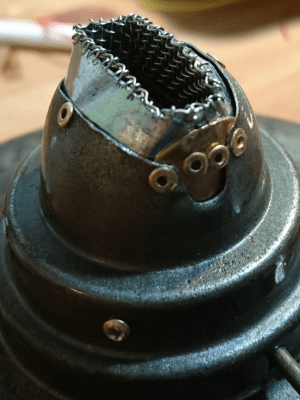
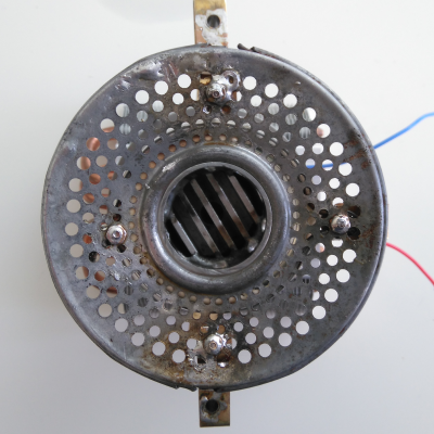
5.1 : Burner
5.2: Air-fuel mixing mesh
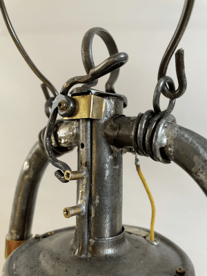
5.3 – 5.3′ : Generator holding arms
5.3.1 – 5.3.1′: Threaded rod section (secure generator on chassis)
5.8 – 5.8′: Generator stabilizers
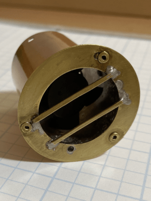
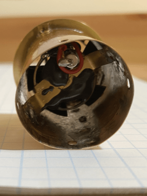
5.9: Burner Fan
5.10: Lever
5.10.A: Latching position A (ignition)
5.10.B: Latching position B (Warm up)
GENERATOR MODULE
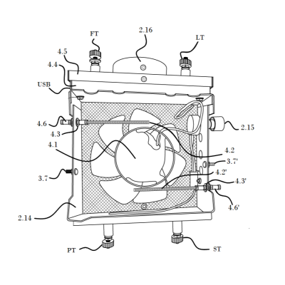
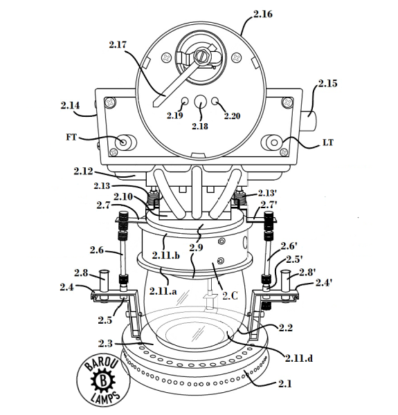 LT: Lights Terminal
FT: (Burner) Fan Terminal
2.1: Base plate
2.2: Glass globe
2.6: Generator securing threaded rods
2.8: Outer Tubes (chassis threaded arms go there)
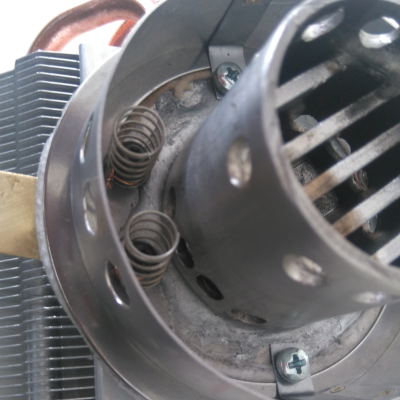
2.9: Heat Exchanger
2.10: Thermoelectric Generator (Peltier element)
2.12: Heatsink
2.14: Heatsink cover
2.15: Airflow regulator
2.16: Power gauge
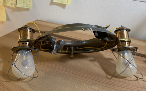
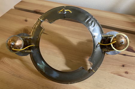
LAMP HOLDER
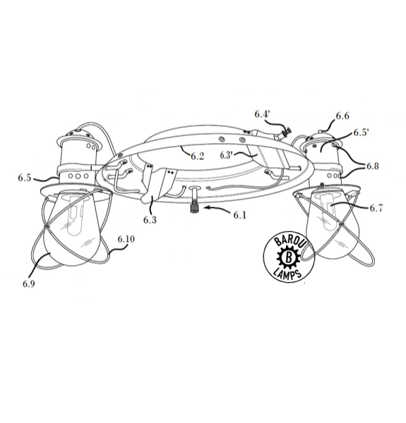 6.1: Electrical terminal
6.3: Semi tubes (lamp holder to chassis stabilizers)
6.4 – 6.4′: Fastener and alignment screws
6.5 – 6.5′: Lamps (modules)
6.6: Heat pipe
6.7: Lighting element
6.9: Frosted glass bulb


